If a linear object attached to an oscillator bobs back and forth within the water, it becomes a source of straight waves. These straight waves have alternating crests and troughs. As viewed on the sheet of paper below the tank, the crests are the dark lines stretching across the paper and the troughs are the bright lines. These waves will travel through the water until they encounter an obstacle - such as the wall of the tank or an object placed within the water. The diagram at the right depicts a series of straight waves approaching a long barrier extending at an angle across the tank of water. The direction that these wavefronts (straight-line crests) are traveling through the water is represented by the blue arrow. The blue arrow is called a ray and is drawn perpendicular to the wavefronts. Upon reaching the barrier placed within the water, these waves bounce off the water and head in a different direction. The diagram below shows the reflected wavefronts and the reflected ray. Regardless of the angle at which the wavefronts approach the barrier, one general law of reflection holds true: the waves will always reflect in such a way that the angle at which they approach the barrier equals the angle at which they reflect off the barrier. This is known as the law of reflection. This law will be discussed in more detail in Unit 13 of The Physics Classroom.
Refraction of Waves
Reflection involves a change in direction of waves when they bounce off a barrier. Refraction of waves involves a change in the direction of waves as they pass from one medium to another. Refraction, or the bending of the path of the waves, is accompanied by a change in speed and wavelength of the waves. In Lesson 2, it was mentioned that the speed of a wave is dependent upon the properties of the medium through which the waves travel. So if the medium (and its properties) is changed, the speed of the waves is changed. The most significant property of water that would affect the speed of waves traveling on its surface is the depth of the water. Water waves travel fastest when the medium is the deepest. Thus, if water waves are passing from deep water into shallow water, they will slow down. And as mentioned in the previous section of Lesson 3, this decrease in speed will also be accompanied by a decrease in wavelength. So as water waves are transmitted from deep water into shallow water, the speed decreases, the wavelength decreases, and the direction changes.
This boundary behavior of water waves can be observed in a ripple tank if the tank is partitioned into a deep and a shallow section. If a pane of glass is placed in the bottom of the tank, one part of the tank will be deep and the other part of the tank will be shallow. Waves traveling from the deep end to the shallow end can be seen to refract (i.e., bend), decrease wavelength (the wavefronts get closer together), and slow down (they take a longer time to travel the same distance). When traveling from deep water to shallow water, the waves are seen to bend in such a manner that they seem to be traveling more perpendicular to the surface. If traveling from shallow water to deep water, the waves bend in the opposite direction. The refraction of light waves will be discussed in more detail in a later unit of The Physics Classroom.
Diffraction of Wave
Reflection involves a change in direction of waves when they bounce off a barrier; refraction of waves involves a change in the direction of waves as they pass from one medium to another; and diffraction involves a change in direction of waves as they pass through an opening or around a barrier in their path. Water waves have the ability to travel around corners, around obstacles and through openings. This ability is most obvious for water waves with longer wavelengths. Diffraction can be demonstrated by placing small barriers and obstacles in a ripple tank and observing the path of the water waves as they encounter the obstacles. The waves are seen to pass around the barrier into the regions behind it; subsequently the water behind the barrier is disturbed. The amount of diffraction (the sharpness of the bending) increases with increasing wavelength and decreases with decreasing wavelength. In fact, when the wavelength of the waves is smaller than the obstacle, no noticeable diffraction occurs.
Diffraction of water waves is observed in a harbor as waves bend around small boats and are found to disturb the water behind them. The same waves however are unable to diffract around larger boats since their wavelength is smaller than the boat. Diffraction of sound waves is commonly observed; we notice sound diffracting around corners, allowing us to hear others who are speaking to us from adjacent rooms. Many forest-dwelling birds take advantage of the diffractive ability of long-wavelength sound waves. Owls for instance are able to communicate across long distances due to the fact that their long-wavelength hoots are able to diffract around forest trees and carry farther than the short-wavelength tweets of songbirds. Diffraction is observed of light waves but only when the waves encounter obstacles with extremely small wavelengths (such as particles suspended in our atmosphere). Diffraction of sound waves and of light waves will be discussed in a later unit of The Physics Classroom Tutorial.
Reflection, refraction and diffraction are all boundary behaviors of waves associated with the bending of the path of a wave. The bending of the path is an observable behavior when the medium is a two- or three-dimensional medium. Reflection occurs when there is a bouncing off of a barrier. Reflection of waves off straight barriers follows the law of reflection. Reflection of waves off parabolic barriers results in the convergence of the waves at a focal point. Refraction is the change in direction of waves that occurs when waves travel from one medium to another. Refraction is always accompanied by a wavelength and speed change. Diffraction is the bending of waves around obstacles and openings. The amount of diffraction increases with increasing wavelength.
Antenna Type Example
A parabolic antenna is an antenna that uses a parabolic reflector, a curved surface with the cross-sectional shape of a parabola, to direct the radio waves. The most common form is shaped like a dish and is popularly called a dish antenna or parabolic dish. The main advantage of a parabolic antenna is that it has high directivity. It functions similarly to a searchlight or flashlight reflector to direct the radio waves in a narrow beam, or receive radio waves from one particular direction only. Parabolic antennas have some of the highest gains, meaning that they can produce the narrowest beamwidths, of any antenna type.[1][2] In order to achieve narrow beamwidths, the parabolic reflector must be much larger than the wavelength of the radio waves used,[2] so parabolic antennas are used in the high frequency part of the radio spectrum, at UHF and microwave (SHF) frequencies, at which the wavelengths are small enough that conveniently-sized reflectors can be used.
Parabolic antennas are used as high-gain antennas for point-to-point communications, in applications such as microwave relay links that carry telephone and television signals between nearby cities, wireless WAN/LAN links for data communications, satellite communications and spacecraft communication antennas. They are also used in radio telescopes.
The other large use of parabolic antennas is for radar antennas, in which there is a need to transmit a narrow beam of radio waves to locate objects like ships, airplanes, and guided missiles, and often for weather detection.[2] With the advent of home satellite television receivers, parabolic antennas have become a common feature of the landscapes of modern countries.[2]
The parabolic antenna was invented by German physicist Heinrich Hertz during his discovery of radio waves in 1887. He used cylindrical parabolic reflectors with spark-excited dipole antennas at their focus for both transmitting and receiving during his historic experiments.
It is possible to use one of a variety of different feed arrangements when using a parabolic reflector antenna.
The different feed arrangements provide a considerable degree of flexibility and enable different applications to gain the most from the use of the antenna.It is worth noting that the actual antenna element within the overall parabolic reflector antenna, i.e. the device that interfaces the transmission line or waveguide containing the radio-frequency energy to free space, is the feed element for the parabolic reflector antenna. The reflector surface itself is entirely passive.
Pulse Modulation Types
Pulse Amplitude Modulation Pulse-amplitude modulation (PAM), is a form of signal modulation where the message information is encoded in the amplitude of a series of signal pulses. It is an analog pulse modulation scheme in which the amplitudes of a train of carrier pulses are varied according to the sample value of the message signal. Demodulation is performed by detecting the amplitude level of the carrier at every single period.
The pulse amplitude modulated signal, will follow the amplitude of the original signal, as the signal traces out the path of the whole wave. In natural PAM, a signal sampled at the Nyquist rate is reconstructed, by passing it through an efficient Low Pass Frequency (LPF) with exact cutoff frequency
There are two types of pulse amplitude modulation:
Single polarity PAM: In this a suitable fixed DC bias is added to the signal to ensure that all the pulses are positive.
Double polarity PAM: In this the pulses are both positive and negative.
Pulse-amplitude modulation is widely used in modulating signal transmission of digital data, with non-baseband applications having been largely replaced by pulse-code modulation, and, more recently, by pulse-position modulation.
In particular, all telephone modems faster than 300 bit/s use quadrature amplitude modulation (QAM). (QAM uses a two-dimensional constellation).
The number of possible pulse amplitudes in analog PAM is theoretically infinite. Digital PAM reduces the number of pulse amplitudes to some power of two. For example, in 4-level PAM there are {\displaystyle 2^{2}} possible discrete pulse amplitudes; in 8-level PAM there are {\displaystyle 2^{3}} possible discrete pulse amplitudes; and in 16-level PAM there are {\displaystyle 2^{4}} possible discrete pulse amplitudes.
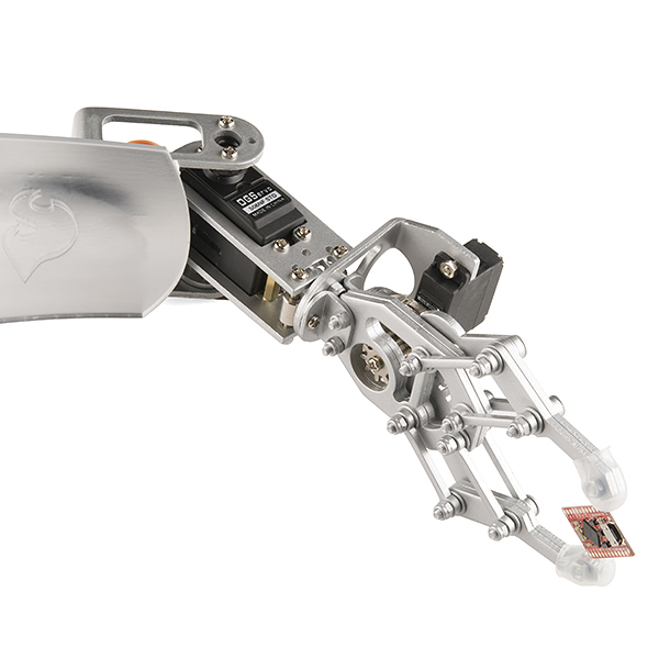
Pulse Width Modulation Pulse Width Modulation (PWM) is a fancy term for describing a type of digital signal. Pulse width modulation is used in a variety of applications including sophisticated control circuitry. A common way we use them here at SparkFun is to control dimming of RGB LEDs or to control the direction of a servo motor. We can accomplish a range of results in both applications because pulse width modulation allows us to vary how much time the signal is high in an analog fashion. While the signal can only be high (usually 5V) or low (ground) at any time, we can change the proportion of time the signal is high compared to when it is low over a consistent time interval.
Robotic claw controlled by a servo motor using pulse-width modulation
Suggested Reading
Some background tutorials you might consider first:
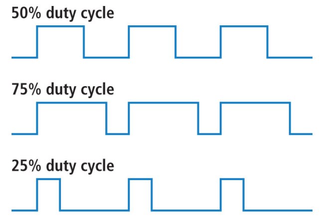
When the signal is high, we call this "on time". To describe the amount of "on time" , we use the concept of duty cycle. Duty cycle is measured in percentage. The percentage duty cycle specifically describes the percentage of time a digital signal is on over an interval or period of time. This period is the inverse of the frequency of the waveform.
If a digital signal spends half of the time on and the other half off, we would say the digital signal has a duty cycle of 50% and resembles an ideal square wave. If the percentage is higher than 50%, the digital signal spends more time in the high state than the low state and vice versa if the duty cycle is less than 50%. Here is a graph that illustrates these three scenarios: 50%, 75%, and 25% Duty Cycle Examples
100% duty cycle would be the same as setting the voltage to 5 Volts (high). 0% duty cycle would be the same as grounding the signal.
Examples
You can control the brightness of an LED by adjusting the duty cycle.
PWM used to control LED brightness
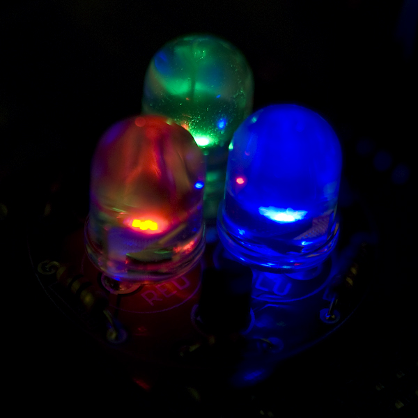
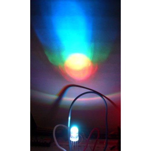
With an RGB (red green blue) LED, you can control how much of each of the three colors you want in the mix of color by dimming them with various amounts. Basics of color mixing
If all three are on in equal amounts, the result will be white light of varying brightness. Blue equally mixed with green will get teal. As slightly more complex example, try turning red fully on, and green 50% duty cycle and blue fully off to get an orange color.
PWM can be used to mix RGB color
The frequency of the square wave does need to be sufficiently high enough when controlling LEDs to get the proper dimming effect. A 20% duty cycle wave at 1 Hz will be obvious that it’s turning on and off to your eyes meanwhile, 20% duty cycle at 100 Hz or above will just look dimmer than fully on. Essentially, the period can not be too large if you’re aiming for a dimming effect with the LEDs.
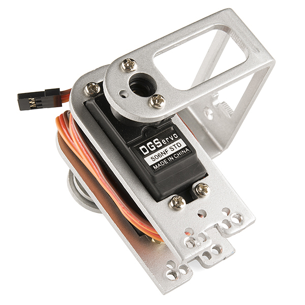
You can also use pulse width modulation to control the angle of a servo motor attached to something mechanical like a robot arm. Servos have a shaft that turns to specific position based on its control line. Our servo motors have a range of about 180 degrees.
Frequency/period are specific to controlling a specific servo. A typical servo motor expects to be updated every 20 ms with a pulse between 1 ms and 2 ms, or in other words, between a 5 and 10% duty cycle on a 50 Hz waveform. With a 1.5 ms pulse, the servo motor will be at the natural 90 degree position. With a 1 ms pulse, the servo will be at the 0 degree position, and with a 2 ms pulse, the servo will be at 180 degrees. You can obtain the full range of motion by updating the servo with an value in between.
PWM used to hold a servo motor at 90 degrees relative to its bracket
Resources and Going Further
Pulse width modulation is used in a variety of applications particularly for control. You already know it can be used for the dimming of LEDs and controlling the angle of servo motors and now you can begin to explore other possible uses. If you feel lost, feel free to check out the SparkFun Inventor's Kit which has examples using pulse width modulation. If you're ready to jump into coding immediately and have an Arduino, look at the PWM coding example here.
Pulse-Code Modulation Modulation is the process of varying one or more parameters of a carrier signal in accordance with the instantaneous values of the message signal.
The message signal is the signal which is being transmitted for communication and the carrier signal is a high frequency signal which has no data, but is used for long distance transmission.
There are many modulation techniques, which are classified according to the type of modulation employed. Of them all, the digital modulation technique used is Pulse Code Modulation (PCM).
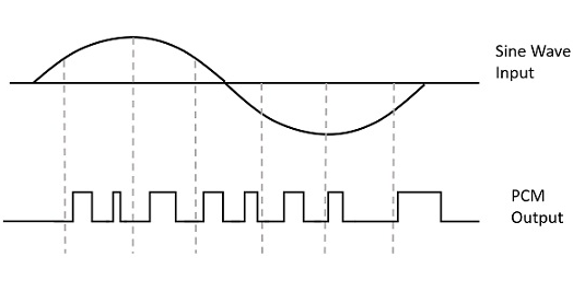
A signal is pulse code modulated to convert its analog information into a binary sequence, i.e., 1s and 0s. The output of a PCM will resemble a binary sequence. The following figure shows an example of PCM output with respect to instantaneous values of a given sine wave.
Instead of a pulse train, PCM produces a series of numbers or digits, and hence this process is called as digital. Each one of these digits, though in binary code, represent the approximate amplitude of the signal sample at that instant.
In Pulse Code Modulation, the message signal is represented by a sequence of coded pulses. This message signal is achieved by representing the signal in discrete form in both time and amplitude.
Basic Elements of PCM
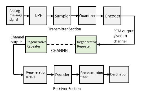
The transmitter section of a Pulse Code Modulator circuit consists of Sampling, Quantizing and Encoding, which are performed in the analog-to-digital converter section. The low pass filter prior to sampling prevents aliasing of the message signal.
The basic operations in the receiver section are regeneration of impaired signals, decoding, and reconstruction of the quantized pulse train. Following is the block diagram of PCM which represents the basic elements of both the transmitter and the receiver sections.
Low Pass Filter
This filter eliminates the high frequency components present in the input analog signal which is greater than the highest frequency of the message signal, to avoid aliasing of the message signal.
Sampler
This is the technique which helps to collect the sample data at instantaneous values of message signal, so as to reconstruct the original signal. The sampling rate must be greater than twice the highest frequency component W of the message signal, in accordance with the sampling theorem.
Quantizer
Quantizing is a process of reducing the excessive bits and confining the data. The sampled output when given to Quantizer, reduces the redundant bits and compresses the value.
Encoder
The digitization of analog signal is done by the encoder. It designates each quantized level by a binary code. The sampling done here is the sample-and-hold process. These three sections (LPF, Sampler, and Quantizer) will act as an analog to digital converter. Encoding minimizes the bandwidth used.
Regenerative Repeater
This section increases the signal strength. The output of the channel also has one regenerative repeater circuit, to compensate the signal loss and reconstruct the signal, and also to increase its strength.
Decoder
The decoder circuit decodes the pulse coded waveform to reproduce the original signal. This circuit acts as the demodulator.
Reconstruction Filter
After the digital-to-analog conversion is done by the regenerative circuit and the decoder, a low-pass filter is employed, called as the reconstruction filter to get back the original signal.
Hence, the Pulse Code Modulator circuit digitizes the given analog signal, codes it and samples it, and then transmits it in an analog form. This whole process is repeated in a reverse pattern to obtain the original signal.


No comments:
Post a Comment